ADVERTISEMENTS:
This article throws light upon the four main components of a spillway. The components are: 1. Control Structure 2. Conveyance Structure 3. Terminal Structure 4. Entrance and Exit Channels.
Component # 1. Control Structure:
The control structure of a spillway regulates and controls the outflows from the reservoir. It is usually located at the upstream end of the spillway, and consists of some form of overflow crest. In some cases, however, the control may be at the downstream end.
For example, in a morning glory spillway, the downstream tunnel rather than the crest controls the flow at higher heads. In plan, the overflow crests can be straight, curved, U-shaped, semicircular or circular. The crest can be sharp, broad, ogee-shaped or of other cross-section.
Component # 2. Conveyance Structure:
ADVERTISEMENTS:
The outflow released through the control structure is usually conveyed to the downstream river channel through a discharge channel or waterway. Free fall spillways, however, do not require any such conveyance structure.
The conveyance structure can be the downstream face of the dam (if the spillway has been constructed in the main body of the dam), or an open channel excavated along the ground surface of one of the abutments, or an underground tunnel excavated through one of the abutments. The conveyance structure too can have a variety of cross-sections depending upon the geologic and topographic characteristics of the site and hydraulic requirements.
Component # 3. Terminal Structure:
When water flows from the reservoir level to the downstream river level, the static energy is converted into kinetic energy which, if not properly dissipated, may cause enough scour near the toe of the dam to damage the dam, spillway and other structures.
Therefore, suitable stilling basins at the downstream end of the spillway are usually provided so that the excess kinetic energy is destroyed, and the discharge into the river does not result in objectionable scour.
ADVERTISEMENTS:
The excess kinetic energy can be dissipated by a hydraulic jump basin, a roller bucket or some other suitable energy dissipator or absorber. In some cases, however, the overflowing water may be delivered directly to the stream if the stream bed consists of erosion-resistant bed rock.
The incoming jet should always be projected some distance downstream from the end of the structure by means of structures, such as flip buckets or cantilevered extensions.
Hydraulic jump is one of the best means to dissipate the excess energy of the falling water. Hence, wherever the tail water conditions are suitable for the formation of hydraulic jump, it is usual to provide hydraulic jump type stilling basins which have been comprehensively studied.
Alternatively, bucket type energy dissipators are provided. When the tail water depth is either too small or too large for the formation of hydraulic jump, the high amount of energy at the toe of spillway can be dissipated by the use of bucket type energy dissipators.
These can be either:
(i) Trajectory (or deflector) bucket, or
(ii) Roller (or submerged) bucket energy dissipators.
(a) Trajectory (or Deflector) Bucket:
When tail water depth is lower than the depth required for the jump formation and the bed of the river channel is composed of sound rock capable of withstanding the impact of trajectory jet, trajectory bucket (also known as deflector or ski-jump bucket) (Fig. 11.6) is generally used as energy dissipator.
The incoming jet of water leaves the bucket as free-discharging upturned jet and falls into the stream channel some distance downstream from the end of the spillway. The upturned jet gets split into number of bubbles or smaller jets. The energy is dissipated on account of the increased air resistance because of splitting of the jet as well as the impact against water and the channel bed downstream.
(b) Roller (or submerged) Bucket:
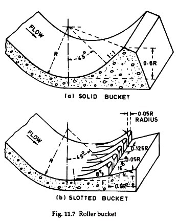
Roller bucket is used when tail water depth is greater than 1.1 times the required conjugate depth for the formation of the hydraulic jump and the river bed rock is good. Roller buckets can be either solid or slotted (Fig. 11.7). The general hydraulic action responsible for the dissipation of energy is shown in Fig. 11.8.
The energy dissipates through the formation of two rollers; one is on the surface of the bucket and moves anticlockwise (considering that the flow is to the right), and the other is a ground roller moving in a clockwise direction and which forms immediately downstream of the bucket (Fig. 11.8). The intermingling of the incoming flow with the rollers as well as the movements of the rollers dissipate the energy of the water effectively and prevent excessive scouring downstream of the bucket.
Component # 4. Entrance and Exit Channel:
Entrance channel conveys water from the reservoir to the control structure, while the exit channel conveys the flow from the terminal structure to the stream channel downstream of the dam.
Entrance and exit channels are, however, not required for such spillways which draw water directly from the reservoir, and discharge it directly into the stream channel as in the case of overflow spillway in a concrete dam. In spillways which are placed along the abutments or located near saddles or ridges, entrance and exit channels would be needed.


